Introduction
When we model shapes, we need to choose which high-level modeling elements to adopt. Consider, e.g., the three-dimensional object (partially showed) in Fig. [fig:ublock]. We can describe it as being characterized by a U-shape. Alternatively, in addition to the shape, we can understand it as bearing two protrusions or a slot. These representational alternatives appear to be all viable.
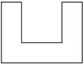
Sketch of the section of a 3D object
The scenario above is a simplification of what commonly happens in the context of Computer-Aided Design (CAD). By means of CAD systems, indeed, we can rely on different approaches for shape representation, but the systems are not helpful to decide which elements we should include in a model, e.g., only shapes or also additional things.
From a knowledge representation, engineering, and cognitive perspective it makes a great difference to explicitly take protrusions or slots, among others, into account. First, because we conceive and perceive them as “first-order citizens” of our world (Bertamini and Casati 2014), which are cognitively selected because of their properties. Second, because they can be helpful for certain modeling tasks. These considerations imply some consequences. Indeed, once we admit, e.g., protrusions in our domain, we need to understand what they are, as well as the fact that different agents commit to them but in different manners.
We take here a knowledge engineering stance and focus on the choice of which modeling elements to adopt for the representation of shapes. In Sect. [sec:mp] we introduce two approaches for shape modeling that are common in CAD contexts. These approaches provide the basic concepts which are further discussed in Sect. [sec:cla] to understand how complex shapes result from patterns of simpler shapes. Finally, Sect. [sec:onto] introduces an high-level ontological analysis to to characterise protrusions and the like from an ontological perspective.
Modeling alternatives
Consider the wing rib representation showed in Fig. [fig:rib], a structural element of the skeleton of an airplane wing.
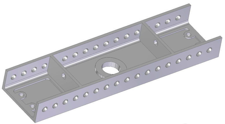
3D model of wing rib
When we look at the wing rib from a pure morphological stance, we consider in the first stance the (complex) shape that characterizes the object itself. At the representational level, its description can be given in different manners, e.g., in a pure qualitative setting, or by combining mereological theories for parthood representation with geometric notions, or, more standardly, by means of an analytic geometric formalism. From an engineering modeling perspective, CAD systems for mechanical design (MCAD) allow to represent the wing rib by means of basic elements such as faces, edges and vertexes, as well as geometric and topological constraints. The resulting morphology is then mapped into an appropriated data structure, which is referred to as boundary representation (B-rep) (Stroud and Nagy 2011).
In all these approaches, the final shape of the wing rib can be obtained in different manners and at different levels of detail, e.g., by flattening the shape to low-level modeling constructs (edges, etc.), or by combining various and possibly simpler shapes, which can recursively result from other constructs. In the latter case, the choice of which shapes to adopt is not however straightforward and different modelers may easily come to the same final shape by means of different (simpler) ones. Additionally, pure morphological, B-rep based approaches run the risk of not making explicit relevant information. Looking at Fig. [fig:rib], for example, we may want to acknowledge for holes and mid ribs. As suggested in Jowers and Earl (Jowers and Earl 2014), this means that we identify in the wing rib those (generally speaking) structural aspects that are relevant for some reasons. The recognition of holes and the like however presupposes that certain modeling constructs are given some kind of unity and are identified as entities of certain types, therefore satisfying identity criteria. On the other hand, this knowledge is not necessarily conveyed in morphological approaches and needs to be explicitly conveyed.
In engineering, this second modeling requirement is addressed in feature-based approaches, which have been proposed with the explicit purpose of conceiving and developing product models by abstracting from low-level geometric modeling elements and relying, instead, on features (e.g., things like holes and ribs, among others) (Stroud and Nagy 2011). Accordingly, features are whole entities that can be associated with disparate properties —e.g., shape or functional properties— and are commonly understood as modeling constructs to represent “the engineering significance of the geometry of a part” (Bronsvoort and Jansen 1993).1 The introduction of feature-based approaches has been an important improvement of engineering 3D modeling. MCAD systems, however, only include macro-modeling elements to ease model creation but neither provide explicit feature definitions, nor their geometric/topological properties are preserved along the overall modeling process. Moreover, as pointed out in the introduction, computer-aided systems are not per se helpful to decide whether the representation of some features should be preferred over the others. Feature representation is indeed context-dependent and different experts recognize the presence of different features in the same model (Jowers and Earl 2014). For example, looking again at Fig. [fig:rib], from a mechanical perspective the trade-off between deformation and weight explains a section shape that minimizes the deformation on a prescribed axis, therefore the presence of the mid ribs, as well as the several holes on the lateral surface, and the one at the center. From a manufacturing perspective, the object is machined from a blank, therefore by removing material until reaching the described product. It becomes clear that the two interpretations specify different features: structural features in the first case, machined features in the second one.
Understanding \((i)\) how a complex shape results from the composition of other, simpler, shapes, \((ii)\) what are the ontological properties that these shapes carry, especially when they are looked from a feature perspective, and \((iii)\) how to make sense of multiple-perspectives on the same shapes/features are problems that are not restricted to the engineering domain, but more generally apply to the overall context of shape representation. We shall address the first two issues in the remaining sections, while leaving the third one to future work.
Patterns for shape representation
In cognitive science, the model of geons of Biederman (Biederman 1987) and the hierarchical model of cylinders of Marr and Nishihara (Marr and Nishihara 1978) have been widely used to specify complex shapes. In these approaches, the overall shape of an object is approximated by a primitive shape (e.g., a cylinder or a parametric volume) that can be decomposed into smaller ones—approximating the shape of some relevant parts of the whole—structured in a given way. The decomposition process can be recursively applied.2 One could think to apply this idea to shape in general, i.e., complex shapes could be described by considering the way in which basic shapes are recursively (geometrically, topologically, mereologically, etc.) structured. For instance, one could think that the shapes of the objects represented in Fig. [fig:ublock]–[fig:rib] are complex, and therefore structured in simpler (basic) ones. Hence shapes could be understood as sorts of distributional properties (Parsons 2004), e.g., in the case of colors, being polka-dotted. As observed by Jowers (Jowers and Earl 2014), the way the designers build complex shapes starting from simple ones is important for the understanding of the design itself since it may reflect, for instance, functional requirements or the way in which designers think about the shapes themselves.
![Different shapes for the object in Fig. [fig:ublock]](images/ObjU_edge.png)
Different shapes for the object in Fig. [fig:ublock]
Let us consider the object in Fig. [fig:ublock]. Fig. [fig:ObjU] shows different shapes that describe the morphology of this object. As in the case of the hierachical model of Marr and Nishihara, we assume that, at a given level of granularity, the shape of the whole object is “approximated” by a basic one, which we assume to be a B-rep. In Fig. [fig:ObjU].a one has a single basic (unstructured) shape, a single level of granularity, i.e., a single B-rep (dots represent edges, while lines represent faces). Vice versa, Fig. [fig:ObjU].b depicts the case of a complex shape obtained by structuring the basic shapes \({\sf A_b}\) and \({\sf B_b}\) according to a given geometrical pattern represented by the dotted line.3 First, note that the shape \({\sf B_b}\) is used two times in Fig. [fig:ObjU].b, i.e., the spatial pattern requires the same shape \({\sf B_b}\) to be linked in two different ways to \({\sf A_b}\). In terms of colors, one can think to the pattern of red/blue/red strips, where red occurs twice. Second, the existence of the shape does not necessarily implies the existence of an object with this shape, i.e., the designed product may be still atomic (i.e., without any component), hence the existence of a component for each basic shapes is not mandatory. Third, the shape in Fig. [fig:ObjU].b is intended to capture two levels of granularity. The finer one is given in terms of the spatial distribution of the shapes \({\sf A_b}\) and \({\sf B_b}\). The coarser one is just a basic shape that is implicit in the picture, and which corresponds to the B-rep in Fig. [fig:ObjU].a. One can thus think that the shape in Fig. [fig:ObjU].b is a refinement of the one in Fig. [fig:ObjU].a because it adds some structural information that \({\sf A_a}\) discards. Clearly, \({\sf A_a}\) can be refined in alternative ways, e.g., in Fig. [fig:ObjU].c one starts from different shapes and a different pattern. Note that the shapes in Fig. [fig:ObjU].b and Fig. [fig:ObjU].c are different even though at the coarser level they coincide with \({\sf A_a}\). We can re-iterate the process of decomposition introducing more refined shapes distributions.
Considering features, one can think that, e.g., a cubical protuberance or a cubical hole are specific kinds of shapes that differ from other cubical shapes, because of the way in which they are related to other shapes. Following this reasoning, a cubical protuberance can be defined as a cubical shape plus a pattern specifying how the shape must be linked to another one. Fig. [fig:ObjU].d shows the graphical notation for a protuberance where the depicted pattern means that the lower face of \({\sf B_d}\) must be connected (in a certain way) to a face of the host-shape. The case of holes (aka hole-shapes) is more complex than protuberances, since to obtain the B-rep that approximates a complex holed-shape (i.e., a complex shape with a hole) the B-rep of the hole has to be discarded from the whole. In Fig. [fig:ObjU], we represent (basic) holes with grey edges and surfaces. If the design explicitly refers to holes, the shape \({\sf A_a}\) can be refined as in Fig. [fig:ObjU].e, where \({\sf C_e}\) is a (basic) prismatic hole. Accordingly, the upper face of \({\sf C_e}\) is not part of the B-rep in \({\sf A_a}\). Furthermore, the pattern that specifies the hole includes also constraints on the way the three shapes it plugs-in are connected.
The ontological framework
We identified so far some shapes in the context of patterns giving rise to shape-features. Besides pure geometric or topological properties, we are now interested in characterizing the properties that distinguish, let us say, a protrusion from a hole. Indeed, once we admit them into the inventory of our domain, we need to understand what they are. For this purpose, we adopt a minimal ontological framework distinguishing between objects, parasitic objects (parasite, for short) and qualities. Objects are assumed to extended in space and are possibly made of some material; examples are bricks. Parasitic objects are physical objects that ultimately depend on non-parasites, i.e., they cannot exist if detached from the latter. An example is the head of a bolt.4 Qualities represent objects characteristics, e.g., the color of a bike frame, or the pitch of a threaded screw.
In terms of this framework, physical holes or protrusions fit well with the notion of parasite. E.g., to be a protrusion (or a hole) means to be a protrusion in something else. By “objectifying” features, we have the possibility of representing them along with their characterising qualities, e.g., shapes, without however reducing them to qualities themselves. Additionally, we reflect cognitive but also engineering theories treating features as objects satisfying unity and possibly even identity criteria. We will therefore adopt this approach from now on. Looking at the ontological dependence of parasites, it can be understood as being either specific or generic. In the first case, a feature \(f\) depends on a specific individual \(o\), so that if \(o\) ceases to exist, then \(f\) ceases to exist, too. In the second case, \(f\) depends on some entity (of a certain type), so that \(f\) can survive the replacement of its host.5
Despite this distinction finds its place in ontology (Masolo et al. 2003), it is not straightforward to establish the kind of dependence that a parasite satisfies. Consider, for instance, the hole at the centre of the wing rib in Fig. [fig:rib], call it \(h\). On the one hand, we can assume that as far as \(h\) maintains its identity, given, e.g., in terms of shape or functional properties, it keeps existing although the radical changes that its host may undergo. For example, assume that persistence conditions of the wing rib are given in functional terms, so that it ceases to exist when it cannot exhibit its functionality. If generic dependence is adopted, then \(h\) may continue to exist when the wing rib “passes away”. On the other hand, if specific dependence is adopted, then \(h\) stops existing along with the wing rib. Since from an ontological perspective both views are well motivated, the choice of which kind of dependence to adopt relies on background domain assumptions. In the case of CAD modeling, for instance, specific dependence may be better suited, since each feature is intentionally attached to individual products.
We now need to make sense of the fact that some features are ascribed with materiality. We therefore introduce the notion of material parasite, that is, a parasitic object made of some material. Conversely, an immaterial parasite lacks material constitution. Consider now holes:6 are they material or immaterial parasites? Both views are found in philosophical ontology (Casati and Varzi 1994), as well as in engineering. On the one hand, it is indeed common to refer to holes as voids, which are often ascribed with the functionality of accommodating some other entity, e.g., screws.7 On the other hand, a hole in an object is understood as set of surfaces with a characterising shape. Take again the hole \(h\) in the wing rib. From the latter perspective, \(h\) is the cylindrical surface of the wing rib located in a certain spatial position (within the spatial system relative to the wing rib itself). From the former perspective, \(h\) is the cavity which is (topologically) connected to some of the wing rib surfaces. It is hard to discard one of these views, since—looking at a hole—one may need to represent both a cavity (e.g., in which something can be accommodated) and a surface (possibly made of some material) to which the cavity connects. From an ontological stance, these are however two different entities. We therefore propose to distinguish between cavity-like (or void-like) features as immaterial parasites and the (material) objects to which they connect. Admittedly, this ontological framework is still general and more specific constraints should be added, e.g., to characterize features with functional properties. The introduced distinctions are however helpful to shed some light on the high-level properties that features satisfy. For instance, if—within design modelling contexts—we consider components as products intentionally designed to be possibly related to some other product, then features are not components. Indeed, it is reasonably to assume that a component can exist on its own, whereas—as we saw—the existence of features depends on other entities.8
Conclusions
We addressed some general issues concerning shape modeling. In particular, we saw that shapes can be represented by means of different modeling constructs at different representational layers. B-rep models can be taken as the lowest representational level since they provide a precise specification of morphological properties in terms of vertexes and other low-level geometric constructs. We saw that this approach comes with its own costs, e.g., it does not allow to refer to a certain portion of the shape at stake to attribute it some functional property. Following cognitive science theories and engineering modeling approaches, we considered how to build a more abstract, coarse-grained representational level on the top of B-rep constructs. Accordingly, an overall shape results from the composition of multiple (simpler) shapes, which are spatially arranged according to patterns of spatial distribution. In other words, in this second representational level collections of B-rep elements are assumed to satisfy unity and identity criteria; hence, they form some sort of structured building blocks that can be explicitly selected, composed and characterised with design properties. On the top of these blocks, we built the ontological level to both contextualise them within a larger ontology for objects’ representation and characterise their properties. E.g., we saw that it is common to use protrusions and holes in CAD-based design; at the ontological level we specify what they are, e.g., if and how they distinguish from components. Finally, note that the choice of which building blocks to adopt is up to modelers and their use may rely on different requirements such as the optimisation of the design process, or the specification of functional properties.
Bertamini, M., and R. Casati. 2014. “Figures and Holes.” In Handbook of Perceptual Organization, edited by J. Wagemans, 281–93. Oxford University Press.
Biederman, I. 1987. “Recognition-by-Components: A Theory of Human Image Understanding.” Psychological Review 94 (2). American Psychological Association: 115.
Bronsvoort, W.F., and F.W. Jansen. 1993. “Feature Modelling and Conversion. Key Concepts to Concurrent Engineering.” Computers in Industry 21 (1). Elsevier: 61–86.
Casati, R., and A. Varzi. 1994. Holes and Other Superficialities. Mit Press.
Guarino, N., and C.A. Welty. 2009. “An Overview of OntoClean.” In Handbook on Ontologies, edited by S. Staab and R. Studer, 201–20. Springer.
Jowers, Iestyn, and Chris Earl. 2014. “Shape Interpretation with Design Computing.” In Design Computing and Cognition’12, 343–60. Springer.
Marr, D., and H.K. Nishihara. 1978. “Representation and Recognition of the Spatial Organization of Three-Dimensional Shapes.” Proceedings of the Royal Society of London B: Biological Sciences 200 (1140). The Royal Society: 269–94.
Masolo, C., S. Borgo, A. Gangemi, N. Guarino, and A. Oltramari. 2003. “WonderWeb Deliverable D18.” Laboratory for Applied Ontology ISTC-CNR.
Parsons, J. 2004. “Distributional Properties.” Lewisian Themes. Oxford University Press Oxford, 173–80.
Stroud, I., and H. Nagy. 2011. Solid Modelling and CAD Systems: How to Survive a CAD System. Springer Science & Business Media.
‘Part’ is synonym of ‘product’ in this sentence.↩
Approximation and granularity play a central role in the process of recognizing and representing shapes.↩
\({\sf A}_x\) denotes the basic shape indicated with \({\sf A}\) in Fig. [fig:ObjU].x. In general \({\sf A}_x\) and \({\sf A}_y\) are different in case \(x \neq y\).↩
For the sake of the example, we assume that when the head of a bolt is detached from the bolt, it stops existing as “the head of the bolt”. In this sense, the head is a “parasitic part” of the bolt↩
We call host the entity upon which a parasite depends.↩
The same considerations can be done for features like slots, pockets, etc.↩
See the modeling element IfcFeatureElementSubtraction in the Industry Foundation Classes (IFC); http://www.buildingsmart-tech.org/ifc/IFC4/Add1/html/, last access on July 2017.↩
We assume here a rigid (Guarino and Welty 2009) notion of component. This means that an object is a component for the entire duration of its life, independently from the fact that it is not attached to some other product at a certain time.↩